Chapter 2 – Digital Control of Little Motors
At this point, we can apply power to a motor and it will run. We know how to extend the leads on our motor so it is a useful length. For our next leap, we will need to build the basis of computer control for our little motors. This chapter is a long one…
The Hello World of Computer Control
Let’s start with a simpler project — blinking an LED. This can be done fairly straightforwardly… Consider this circuit:
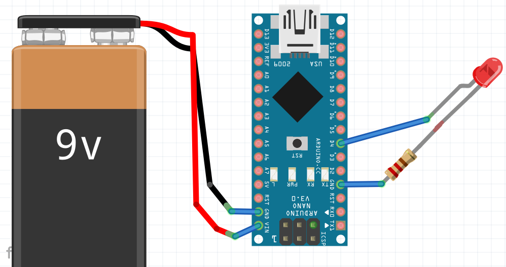
The Vin pin on the Arduno Nano takes between 7-12 volts comfortably and regulates it to the voltages that it needs (3.3v and 5v). A little bit later I describe how I use cell phone/USB chargers and use the 5V and GND pins; this also works fine, but, bypasses many of the protections that are built into the Arduino chip.
The Nano is a 5v device. When a digital pin is set as an output on the Nano, it will go between 0v (if set LOW) and 5v (if set HIGH). The resistor inline with the LED is important, it limits the current that flows through the LED.
With the LED wired to pin 4 as shown I can now write a Arduino program similar to the following:
// setup is called once when the Arduino powers on.
void setup() {
  pinMode(4, OUTPUT);
}

// the loop function runs over and over again forever
void loop() {
  digitalWrite(4, HIGH);  // LED on (apply +5v to pin)
  delay(1000);            // wait 1 second
  digitalWrite(4, LOW);   // LED off (apply 0v to pin)
  delay(1000);            // wait 1 second
}
This works great. The current through the pin can be calculated via Ohm’s law. Voltage=Current * Resistance. So Current = 5V/220ohm ~= 0.023A or 23 mA. The Nano is only capable of doing a MAX of 40 mA from a data pin, so, OK for an LED.
Let’s refine our example a little bit.. First, we would probably want to wire this up with prototyping breadboard. Let’s take a look at that:
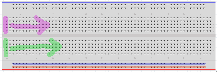
A breadboard is a prototyping tool in which the holes are electronically connected in a logical fashion which I will describe below. By taking advantage of these connections, it is easy to lay out and change a circuit by just moving wires around.
As shown in the above breadboard, the line of 5 pins marked with magenta are electronically connected — these 5 pins are ONLY connected to each other. If we shift 1 column to the right, we get a NEW set of 5 connected pins. This repeats across the entire board.
This also repeats in the blocks of 5 pins on the bottom half — So, the 5 green pins are electronically connected — ONLY To each other and not to the magenta nor to the other pins on the board — and this repeats for each column going across the bottom half of the board.
More advanced boards can have additional features/connections. A common one is shown above: The entire bottom row of pins marked in red is all connected as is the line of pins marked in blue above that. This connectivity repeats on the top of the board.
So, if we were to prototype our LED circuit on the breadboard, it might look like this:
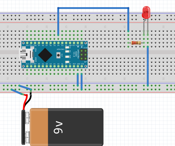
BTW. The 9v is there for clarity, but, most people would run this circuit from the USB connection on their computer — that is what is used to program the board anyway. In our case, the USB has a maximum current of about 500 mA… So, it will drive 1-2 motors, but, after that point we need to have the external power supply.
Interfacing Motors – Transistors as Switches and Diodes for Voltage Protection
There are two problems when we replace the LED in our circuit with a motor:
- The little motors use more current than the LEDs.
- When the motors go on and off, they create voltage spikes which can be dangerous to the Arduino.
So, here are some more parts that will be useful:
- 220 Ohm Resistors or get a kit of lots of resistors
- 2n2222 Transistors
- 4148 Diodes or get a kit of lots of diodes
- Little Breadboards or slightly bigger breadboards
- Jumper Wires.
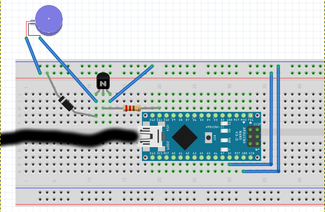
We will be using a transistor as a switch to turn on the power to the motor. A description of transistors as switches is roughly available here or here. `Below is our new schematic…
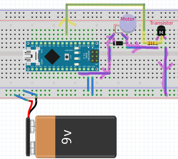
There are a couple of things to notice. The motor does not want to be fed with 9v. In this example, I am feeding it with 5v off the Arduino — the 5v pin is tied to the voltage regular and can provide relatively large amounts of electrical current. The flow of power to the motor is highlighted in magenta — starting at the 5v pin, it flows into the motor, then out through the transistor and on to ground. The transistor, however, will BLOCK current thru it unless a voltage (current) is applied to the center pin, this is provided by the path shown in yellow. So, when we bring the control pin high, the current flows thru the motor, when the control pin is low, current is blocked.
If you like, you can build a little test circuit without the Arduino to see if it works.
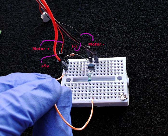
In the above picture, if you touch the orange/white wire to +5v, the motor will turn on — this simulates what it would be if the Arduino was toggling its control pin.
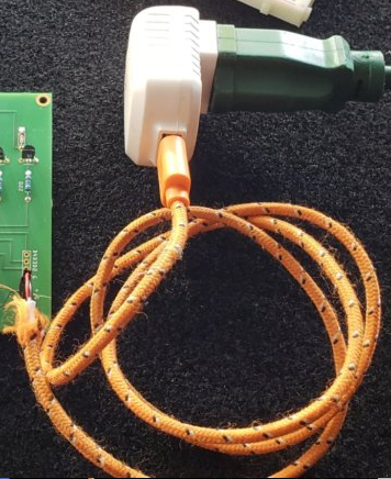
For my 5v supply, I just put crimp on pins onto the end of an old USB cable.
Putting it all together
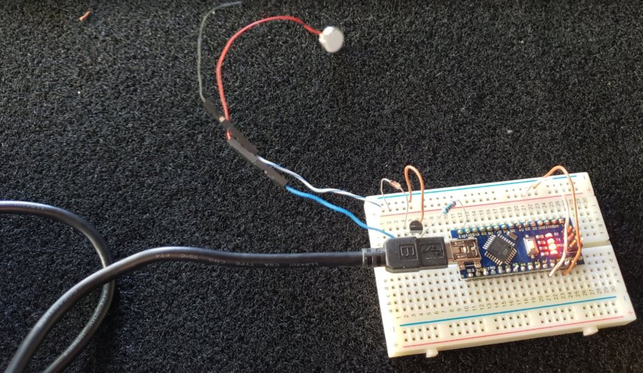
Here is a picture showing the control of a single motor (using PIN D11) with the power supplied by the USB cable. With the motor on, the current measured out at about 120 mA which is well below the limit of ~500mA limit that the Arduino imposes on the USB supply. We will have to do something different when we control multiple motors, but, for now this is good for testing.
We can control this very similarly to our led flashing example above:
// setup is called once when the Arduino powers on.
void setup() {
  pinMode(11, OUTPUT);
}

// the loop function runs over and over again forever
void loop() {
  digitalWrite(11, HIGH); // Motor on (+5v to pin 11)
  delay(1000);            // wait 1 second
  digitalWrite(11, LOW);  // Motor off (0v to pin 11)
  delay(1000);            // wait 1 second
}
Now…. As mentioned, many of these small motors are 3V motors and may not do well at 5V — Symptoms include shortened lives and overheating (which could be bad 😄 ). Since motors are little inductor circuits, it means that they can deal with PWM fairly well. PWM or pulse-width-modulation is a trick in which a electrical source is turned on and off very rapidly so that the average supplied power is lower than if the source were constantly on.

Picture arbitrarily taken from https://wiki.analog.com/university/courses/electronics/electronics-lab-pulse-width-modulation
Mechanical motors are somewhat resilient to PWM power sources and will average out the pulses to so the motor behaves as if it were being powered with a lower voltage.
The Arduino can natively provide PWM on pins 11,10,9,6,5 and 3.
PWM is used by just changing your code slightly — instead of digitalWrite(11,HIGH) (somewhat equivalent to PWM of 100%) we do analogWrite(11,255) (which is PWM of 100%). So, if we know the pin does 5V and we want a PWM value that mimics 3V, we can use X/255 * 5v = 3v, X=153.
And our new code becomes:
// setup is called once when the Arduino powers on.
void setup() {
  pinMode(11, OUTPUT);
}

// the loop function runs over and over again forever
void loop() {
  analogWrite(11, 153);// Motor on (+3v pwm to pin 11)
  delay(1000);         // wait 1 second
  analogWrite(11, 0);  // Motor off (0v to pin 11)
  delay(1000);         // wait 1 second
}
PS….. You can totally control the intensity of the motor by scaling this value. 10% duty cycle will vibrate much less than 100% duty cycle…. IF you were so inclined as to want to generate interesting pulse programs.
There was a lot in this chapter — in Chapter 3 I try to repeat myself to show you that it is really pretty easy…..