Chapter 3: In which we control lots of motors and build our own circuit board.
By now you can construct motors with long leads. You understand the circuitry by which a micro-controller can control a transistor to switch the higher currents a motor might draw. Further, if you read all the way to the end of Chapter 2, you also understand how to use PWM to reduce effective voltage, both for matching your motors to the right current but also to create variable vibration intensities.
In this section I talk about how I wire up multiple motors simultaneously. This chapter will be somewhat less detailed than Chapter 2. In Chapter 2, we talked in length about the circuit that allows a microcontroller pin to control a motor… It is easy to expand what you know to multiple motors using prototype boards, however, if you have a permanent design you can start wiring it up more properly.
Here is my first pass at hand-wiring a 5 channel motor controller:
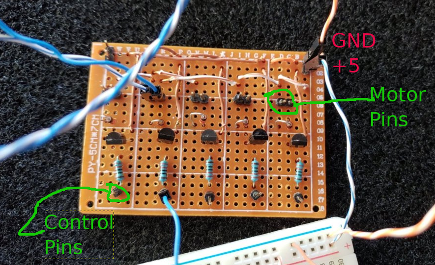
This was somewhat annoying to wire, but, it does work and it is somewhat cleaner than using the prototype boards. I do not show you the underside of this because I am ashamed. But rest assured it is just 5x the control circuit you saw in the previous chapter.
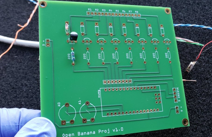
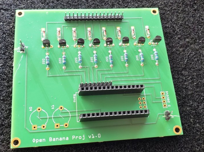
This worked well enough that I did my first circuit board. Designed with the free software Fritzing, you can see it is a much cleaner 8 channel motor driver than my 5 channel hand done breadboard. In addition to the 8 motor channels, there are two 5v power taps (+ G) and breakouts for 2 of the analog lines (A0 A1) as well as 3 of the digital lines (D4 D3 D2). The intent was to provide 5V on either of the 2 +G edge pin pairs and that 5V would drive the Arduino as well as the motors.
The nice thing about the circuit boards is that even if you do the labor “intensive” part of placing and soldering components, it is much less work than trying to wire up all the connecting leads yourself as I did in my hand wired board.
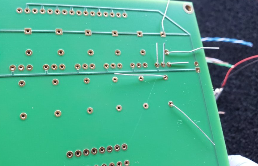
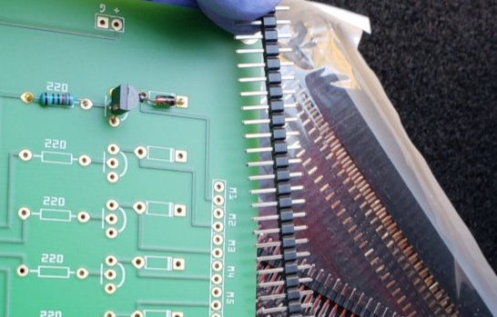
Here is the back side of the board after the components were placed, but, before they were soldered. After soldering each lead, the excess wire is clipped leaving a very clean connection — see the videos on soldering in Chapter 1.
Adding headers pins is also straightforward, using female header pins you can create a socket for your Arduino Nano…
Here is a (mostly) fully populated rev 1 board:
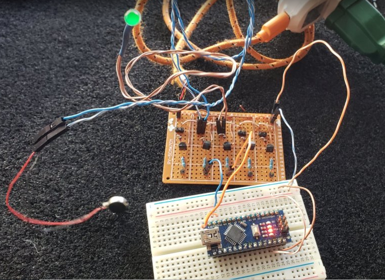
And here is the board in use and you can see how much cleaner/nicer it is to use than the original hand wired board (notice I am not using the 1st motor connection — I am using the connections attached to D11 and D10 so I can do PWM)…. Also note I am using an LED visualizer here…

Many lessons learned from the 1st iteration….
- Initially I used digital pins 12-5 for the motor connections, however, this makes it out of sequence if you only want to use the PWM enabled pins
- I didn’t put in a connection to the Vin pin — While it works fine if supplied with a +5v source on the power supply pins on either edge of the board, there some concern about having both the 5v supply AND the USB connected at the same time. Connecting >=7V on the Vin pin is compatible with the USB data connection and would still allow me to provide 5V to the motors via the 5V pin.
The 2nd revision of the board clustered the PWM pins together, I pulled out some of the non-PWM pins and broke out more of the analog pins. I will update this post after the new board arrives and is tested… In the meantime, if you would like to experiment with Rev 1 of the board, you are welcome to play! (hence the “open” part of the project description, lol). This loads cleanly into Fritzing and the simplified built-it ordering sends the PCB to the company Aisler and it works well and their service is great! — Be aware that 3 boards will cost you about $60…. If the Rev 2 of the board looks good, I will explore trying to create these more cheaply. Also be aware that this was all done in the PCB layout tab on Fritzing, so, the schematic tab looks HORRIBLE.