Chapter 1: Exploring Vibra Motors and Building our tools
In this chapter, I will introduce you to my mini-vibrating motor of choice, I will show you how to start wiring components and introduce you to some of the tricks I use to install connectors, etc.
First (simple) Experiment
Welcome to one of the main workhorses of this HFO/stimulation project…. Mini vibratory motors. Combined with toupee tape (great idea from TekFuture for tape meant for skin) or 3M tissue thin double-sticky tape, you are able, to affix these little guys pretty robustly to places of “interest”.
|
|
|
The mini-motors pack a punch and work well with PWM (explained later if you don’t know) and a wide variety of voltages. The 3M tape shown sticks well until peeled away, however, it is probably not designed for contact with skin. In all cases, tape directly on sensitive areas is not something that I am going to recommend. In the 3 photos above you see the mini motors, the tape and the tape used to attach the mini vibrator to my finger. I assure you that the mini-motor does not come off with normal “activity”.
An easy first experiment would be to test the motors to get a feeling for the sort of what to expect. The easiest way to do that is with a battery. A 3V coin cell battery (2032) works well.
The polarity does not matter… The motor is advertised to work up to 3v (I’ve given it up to 5v which can cause it to heat up a bit). If you were to tape everything in place, that would make vibration goodness… At ~50mA @3V, this would probably run for a few hours on a 2032 battery. FWIW, these things are very quiet… So, if they happened to be under clothes in a bar or restaurant, nobody would be the wiser.
Just to throw it out there, while super fun and compact to have this kinky little unit in your trousers/panties in a public environment, this is not our endpoint — For more private HFO use, the constant stimulus ends up being dulled/ignored by our brain. Its why moving a vibrator around tends to be more effective. In this project, we will be quickly moving from a mere vibrator into the realm of multiple vibrators under computer control creating interesting patterns of stimulation….
Action at a distance — adding length to the motor leads.
One thing we are going to need to deal is that 1-2″ wire leads on the motor are really too short to be useful for our needs. If you do not know how to solder, now is a good time to learn…. Here is a handy list of tools and supplies that you will find useful for all the projects that will be described:
- 22 Ga hookup wire
- Diagonal Cutting Pliers
- Wire Strippers
- Soldering Iron
- Solder
- Heat Shrink Tubing
- “Helping Hands” part holder
And if you wanted to splurge, I find these great for making little connectors:
- Crimping Tool
- Female Pins for 0.1″ housing
- Male Pins for 0.1″ housing
- 1×1 0.1″ Crimp Pin Housings The 1×2 and other sizes are also useful….
If you want to see how to use the crimping tool on the Dupont pins, here is a good video link. Instructables has a nice guide that shows the dimensions involved in the pin (but, note his crimp die is upside down to the one I recommended). I never built the pin guide that is described in the Instructables link, but, honestly, once you get the feel, these pins crimp on pretty painlessly.
If you want a tutorial or two on soldering, here is one and here is another.
Ok, so, its time to add some extensions onto our motors.
- Cut about 6′ of the twin lead hookup wire.
- Strip off about 1″ of insulation from both wires at one end of the 6′ piece of twin lead.
- MAKE SURE you cut and place a piece of heat shrink tubing on the wire before you solder
- Solder the red wire from the motor to the hookup wire. Repeat for the other wire.
- Slide the heat shrink tubing so it covers the connection and then apply light heat (e.g. with a lighter) until the tubing shrinks and holds firm.
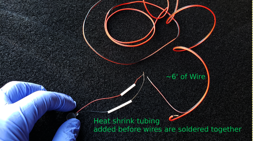
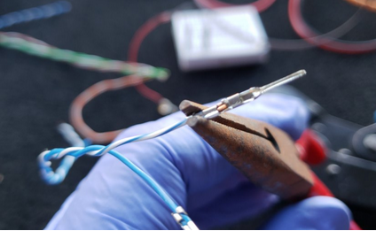
Before the join.
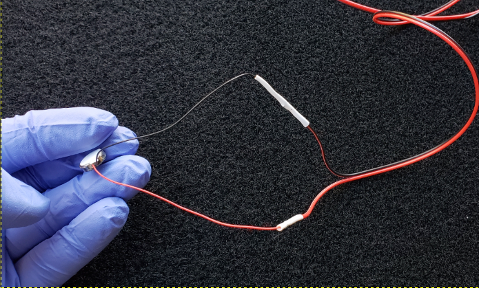
After soldering and heat shrinking
On the other end of the wire, I would recommend putting on some of those 0.1″ crimp pins. You can see the video link above for some techniques. Below are some pictures for reference.
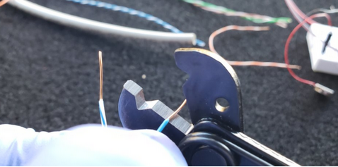
The key to good crimps is getting the right length of exposed wire. I use the flat on my stripper as a rough guide for length — we are shooting for about 2.5-3mm.
Per the video, you want to offset the pin so that the “wings” are about 1-2 mm in from the face. The reason is that if you crimp on the connecting end, it will damage the pin; so, that part all has to hang out the other side of the tool.
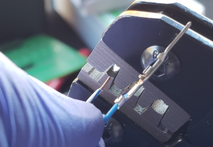
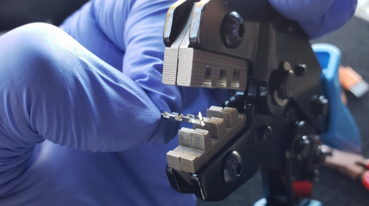
Here you see a crimped pin and a pin about to be crimped. Not that there are 2 crimping surfaces, the wings wrap around the insulation and the smaller fins wrap around the wire. When you insert the wire for crimping, you want to put in _just enough_ that the insulation gets grabbed. Usually the mistake is to put it in too far rather than not far enough.
I find that the pin goes into the housing a little better if I squeeze in on the wings grabbing the insulation.
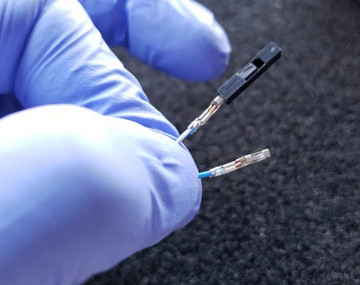
Note the orientation of the pin housing with respect to the pin. Also, notice how the wire in the pins stops before the “locking block” that holds the pin in the pin housing. BTW, this is a female pin; the above photos were with male pins.
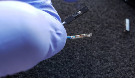
Here is the pin fully seated in the pin housing.
Preparing our Arduinos – Adding the header pins
When you bought the Arduino Nanos, they come as little boards with a separate baggy of header pins. In order to attach the pins, it is very handy to have a little breadboard — here are some more references:
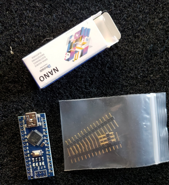
Here is how your Arduino comes..
The easiest why to attach the header pins, it so place the pins in the breadboard, then seat the arduino on top of the pins and then solder the headers in place.
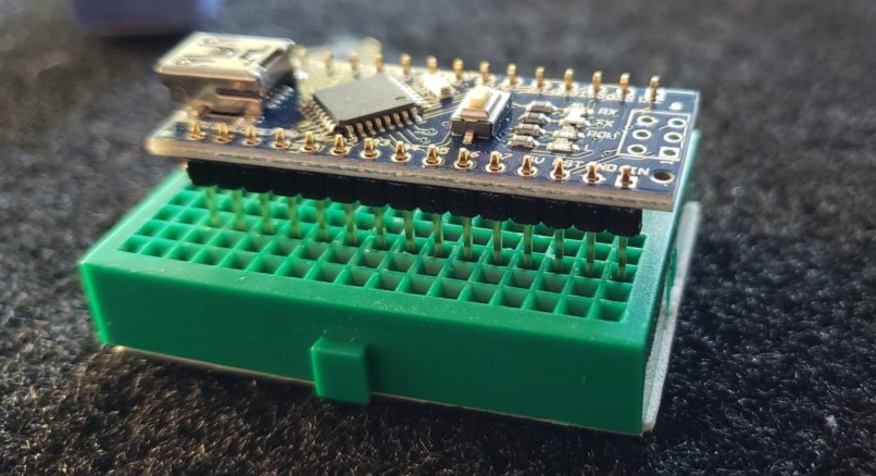
Arduino, not yet fully seated and before soldering.
Onward to Chapter 2