Sidenote 2 – LED Visualizers
You may have noticed that I use LED’s instead of motors on some of the connectors that I take pictures of — LEDs are just more obvious in photos than motors and it is sometimes useful to use these to visualize how the motors will be driven by your programs. Remembering that the LEDs need an some sort of current restriction, usually an inline resistor, to make them work, here is the process that I use:
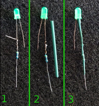
To one of the LED legs attach(1) and solder a 220 ohm resistor clipping the excess lead(2). Now slide on heat shrink tubing that leaves about 1″ of the resistor lead exposed (3).
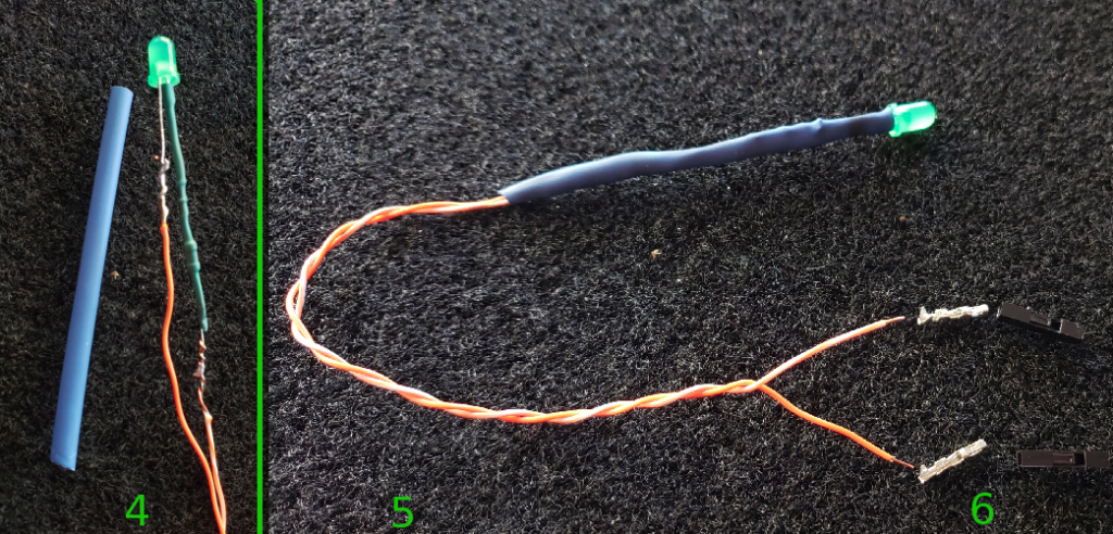
Now, attach wires to the exposed leads, solder in place and cut the excess (4). Slide up a larger piece of shrink wrap and heat into place (5). Finally, attach crimp on pin connectors and apply housings (6).
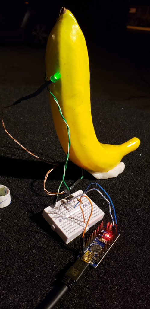
Hey look! Its a open banana visualizer with an actual banana!