Sidenote 1- Revisiting controlling one vibrator…
Let’s look at our simple circuit again…. We are kinda repeating chapter 2 to drive home the point that this is really not that hard :-D.
What have we done?
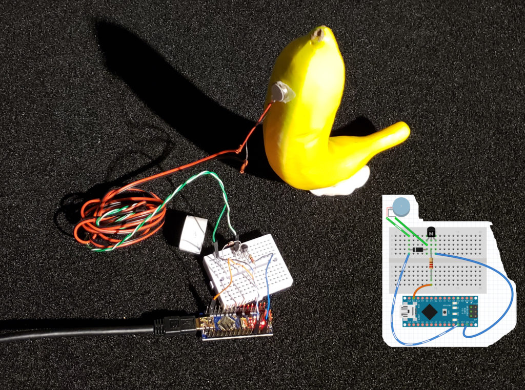
- We got a mini motor. We extended the length of the motor wire by soldering on 6′ extensions and then using heat-shrink tubing to cover the solder joints. We attached the mini motor to an object of interest.
- We used a breadboard to wire up a 2N2222 transistor and a 4148 diode to the motor.
- We are powering the circuit directly off the Arduino Nano +5v and GND pins. We are controlling the transistor via the Arduino D11 pin through a 220 ohm resistor. The Arduino is getting power via the USB cable to the computer — more than sufficient to run probably up to 2-3 motors. We connected all this with the little breadboard
- We installed the Arduino IDE programming environment, selected the Arduino Nano v3.0 as the board (Tools->Board) and selected the ATmega328P as the processor (Tools->Processor). Depending on your board, you will most likely have to select “old bootloader” version. We also needed to select the programming port (Tools->Port:).
- We wrote a little “sketch” (the name for an Arduino program) and uploaded it to the Arduino (Sketch->Upload).
Here is what our 1st sketch looks like (from Chapter 2):
// setup is called once when the Arduino powers on.
 void setup() {
   pinMode(11, OUTPUT);
 }
 // the loop function runs over and over again forever
 void loop() {
   digitalWrite(11, HIGH); // Motor on (+5v to pin 11)
   delay(1000);            // wait 1 second
   digitalWrite(11, LOW);  // Motor off (0v to pin 11)
   delay(1000);            // wait 1 second
 }
It’s that easy!
Can we start complicating things? Sure! For example, that code doesn’t make me happy….
Remember, these are 3v motors, so, 5v is probably a little much. So, instead of:
digitalWrite(11,HIGH)
we should probably do
analogWrite(11,150)
(since 150/255 * 5v ~> 3v).
Also, I dont like remembering which pins are PWM pins or not or what “scale” value I should use. If we complicate our sketch, we might be able to write code that looks like
setrelay(1,255)
and have it automatically translate that into the right pwm values on the right arduino pin..
So, let’s complicate our sketch a bit……
//================================================GLOBALS SECTION
 /\*
    relays\[0\] give the count of the number of relays
    relays\[1..X\] gives the pin numbers for the relays
         11,10,9,6,5,3 are the relays that can do PWM…

 relays will be set with the setrelay command ..
       setrelay takes 0-255, however, that is scaled
       based on the MAXRELAY value -- MAXRELAY is used
       to, for example, scale 0-255 to 0-153 as might be done
       when trying to keep a 3v motor happen when run with 5v
 */
 #define MAXRELAYVAL 150
 #define NUMRELAYS 6
 int relays\[NUMRELAYS+1\]= { NUMRELAYS,11,10,9,6,5,3 };
 int relaystate\[NUMRELAYS+1\];

 //=============================================setrelay
 /*
  I do 3 things:
     1) I make sure that the incoming value is 0..255
     2) I scale the incoming value so that 255-> MAXRELAYVAL
     3) I analog write the scaled value to the relay (PWM)
 */
 void setrelay(int relaynum, int value)
 {
   int foo;
   value = (value > 255 ) ? 255:value;
   value = (value < 0   ) ? 0 : value;

   foo = (int) ( (float) (value) * ((float)MAXRELAYVAL / 255.0));
   analogWrite(relays\[relaynum\],foo);
 }

//=================================================
// the setup routine runs once when you press reset:
 void setup() {
    int x;
    for (x=NUMRELAYS; x>0; x--)
    {
        pinMode(relays\[x\], OUTPUT);
        setrelay(x,0);
    }
 }

 //============================================================
 // the loop routine runs over and over again forever:
 void loop() {
    setrelay(1,255);  // -> pin 11
    delay(1000);
    setrelay(1,0);
    delay(1000);
 }
Much more complicated for the same effect 😄 — but, this is a better base on which to expand our code! BTW, if you change the 2nd delay to 100 its much more exciting 😄.
One final note…
On wiring….. It is not required at all…. You can do the breadboarding and it works fine! But, as we start doing more than one motor, I have found that the circuit board is more robust and a lot cleaner… I talk about this in Chapter 3.
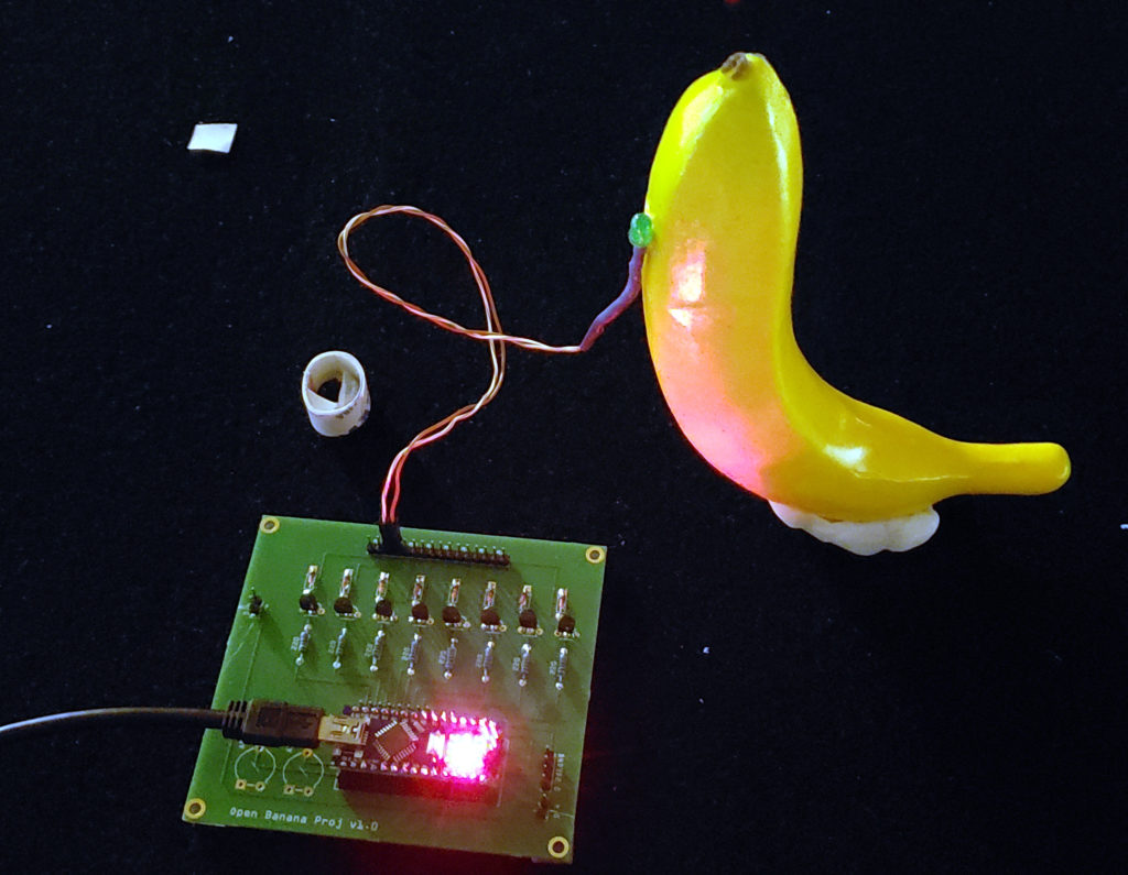
The equivalent circuit to the 1st picture of this post above, using an LED instead of a motor and using the 1.0 version of the circuit board..